BIY Small Vacuum Forming Machine is design special for small size , table ,desktop mini equipment . the advantages of the small Vacuum Forming Machine are suit for DIY products. Now our new best-selling products is
Mini Vacuum Forming Machine which can meet all kinds of personal handwork and
others.
1. BIYV3030 with working size: 300*300*150MM.
2. BIYV4040 with working size: 400*400*150MM.
3. BIY-V4060 with working size: 400*600*250MM.
4. BIY-V6090 with working size: 600*900*300MM.
Small Vacuum Forming Machine Small Vacuum Forming Machine,Mini Star Vacuum Forming Machine,Mini Vacuum Forming Machine,Small Size Vacuum Forming Machine BIY SCIENCE TECHNOLOGY CO., LTD. , http://www.vacuumforming-machine.com
The definition of ripple refers to the AC component that is superimposed on the DC stability in a DC voltage or current.
It mainly has the following disadvantages:
1.1. It is easy to generate harmonics on electrical appliances, and harmonics will create more hazards;
1.2. Reduced power supply efficiency
1.3. Strong ripple can cause surge voltage or current generation, resulting in burning of electrical appliances;
1.4. Will interfere with the logic of digital circuits, affecting their normal operation;
1.5. Will cause noise interference, so that the image equipment, audio equipment can not work properly Second, the ripple, ripple coefficient can be expressed by the effective value or peak value, or with the absolute amount, the relative amount to represent;
The unit is usually: mV
A power supply works in the regulation state, its output is 12V5A, the effective value of the measured ripple is 10mV, this 10mV is the absolute amount of ripple, and the relative quantity, namely ripple coefficient = ripple voltage / output voltage = 10mv/ 12V=0.12%.
Third, the ripple test method 3.1. To limit the bandwidth of the 20M oscilloscope, the voltage is set to PK-PK (also has rms value), remove the clamp and ground wire on the oscilloscope control head (because this clamp and ground will form a loop, like an antenna to receive Noise, introducing unnecessary noise. Using a grounding ring (without using a grounding ring, but taking into account the resulting error), connect a 10 UF electrolytic capacitor and a 0.1 UF ceramic capacitor in parallel with the probe. The probes are tested directly; if the oscilloscope probe is not in direct contact with the output point, it should be measured with a twisted pair or 50Ω coaxial cable.
Fourth, the main classification of the switching power supply ripple The switching power supply output ripple mainly comes from five aspects:
4.1. Input low frequency ripple;
4.2. High-frequency ripple;
4.3. Common mode ripple noise caused by parasitic parameters;
4.4. UHF resonant noise generated during power device switching;
4.5. Ripple noise caused by closed-loop regulation control.
Fifth, the power ripple test ripple is an ac interference signal superimposed on the DC signal, is a very important standard in the power test. Especially for special-purpose power supplies, such as laser power supplies, ripple is one of the key to its fate. Therefore, the power supply ripple test is extremely important.
Power supply ripple measurement methods are roughly divided into two types: one is a voltage signal measurement method; the other is a current signal measurement method.
Generally, for a constant current source or a constant current source with low ripple performance, a voltage signal measurement method can be used. For a constant current source with high ripple performance, current signal measurement is preferred.
The voltage signal measurement ripple refers to measuring the AC ripple voltage signal superimposed on the DC voltage signal with an oscilloscope. For a constant voltage source, the test can directly measure the voltage signal output to the load with a voltage probe. For the constant current source test, the voltage waveform across the sampling resistor is generally measured by using a voltage probe. Throughout the testing process, the oscilloscope settings are the key to sampling the true signal.
The instrument used was a TDS1012B oscilloscope with a voltage measurement probe.
The following settings need to be made before measurement.
1. Channel settings:
Coupling: The choice of channel coupling mode. The ripple is an ac signal that is superimposed on the dc signal. Therefore, if we want to test the ripple signal, we can remove the dc signal and measure the superimposed ac signal directly.
Broadband Limits: Off Probes: Use the voltage probe first. Then select the attenuation ratio of the probe. Must be consistent with the attenuation ratio of the actual probe used, so that the number read from the oscilloscope is real data. For example, if the voltage probe used is set at ×10, then the probe options here must be set to ×10.
2. Trigger settings:
Type: Edge Source: The actual selected channel. For example, if you are going to use the CH1 channel for testing, you should select CH1 here.
Slope: rising.
Trigger mode: If you are watching the ripple signal in real time, select 'Auto' trigger. The oscilloscope will automatically follow the changes in the actual measured signal and display it. At this time, you can also display the measurement value you need in real time by setting the measurement button. However, if you want to capture the signal waveform of a measurement, you need to set the trigger mode to 'normal' trigger. At this point, you also need to set the size of the trigger level. Usually when you know the peak value of the signal you are measuring, set the trigger level to 1/3 of the peak value of the measured signal. If you do not know, the trigger level can be set slightly smaller.
Coupling: DC or AC..., generally AC-coupled.
3. Sample length (seconds/division):
The sampling length setting determines whether the required data can be sampled. When the set sampling length is too large, the high-frequency component in the actual signal will be missed; when the set sampling length is too small, only the local part of the measured actual signal can be seen, and the real actual signal cannot be obtained. So, in the actual measurement, you need to rotate the button back and forth and observe carefully until the displayed waveform is a true and complete waveform.
4 sampling method:
Can be set according to actual needs. For example, if you want to measure the PP value of the ripple, you should choose the peak measurement method. The number of sampling can also be set according to actual needs, which is related to the sampling frequency and sampling length.
5. Measurement:
By selecting the peak measurement of the corresponding channel, the oscilloscope can help you to display the required data in time. At the same time, you can also select the frequency, maximum value, and rms value of the corresponding channel.
By properly setting and regulating the oscilloscope, the desired ripple signal can be obtained. However, during the measurement process, care must be taken to prevent other signals from interfering with the oscilloscope probe itself, so that the measured signal is not sufficiently realistic.
The measurement of the ripple value by the current signal measurement means that the AC ripple current signal superimposed on the direct current signal is measured. For the ripple current index, a relatively high constant current source is required, that is, a constant current source with a relatively small ripple is required, and a direct current signal measurement method can be used to obtain a more realistic ripple signal. Different from the voltage measurement method, the current probe is also used here. For example, continue to use the above oscilloscope, plus a current amplifier and a current probe. At this point, simply measuring the current signal output to the load with a current probe, the current measurement method can be used to measure the output current ripple signal. As with the voltage measurement method, the oscilloscope and current amplifier settings are the key to the ability to sample real signals throughout the test.
In fact, the basic settings and usage of the oscilloscope are the same as those described above. The difference is that the settings of the probe in the channel settings are different. Here, you need to select the current probe method. Then, select the proportion of the probe, which must be the same as the ratio set by the amplifier, so that the number read from the oscilloscope is the real data. For example, if the ratio of the amplifier used is set to 5A/V, then this item of the oscilloscope should also be set to 5A/V. As for the coupling mode of the current amplifier, when the channel coupling of the oscilloscope has been selected as AC coupling, AC or DC can be selected here.
It should be noted that with this method, you need to turn on the oscilloscope first and then turn on the current amplifier. Also, remember to demagnetize the current probe before use.
In addition, measuring the power supply ripple itself is somewhat tricky. Figure 1 shows an example of improper use of an oscilloscope to measure power supply ripple. Several errors have occurred in this example. First is the use of an oscilloscope probe with a long grounding wire. Second, the loop formed by the probe and the ground wire is placed close to the power transformer and the switching element. Finally, the oscilloscope probe is allowed. There is an additional inductance between the output capacitor. The problem with this result is that the picked-up high-frequency component is carried in the measured ripple waveform.
There are many high-speed, large-voltage and current signal waveforms in the power supply that can be easily coupled to the probe, including magnetic field coupling from the power transformer, electric field coupling from the switch node, and generated by the transformer's interwinding capacitance. Common mode current. 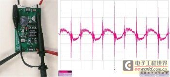
Using correct measurement techniques can actually improve the results of ripple measurements. First, the upper limit of the ripple bandwidth is usually specified to avoid picking up high-frequency noise that exceeds the upper limit of the ripple bandwidth. An appropriate upper bandwidth limit should be set for the oscilloscope used for measurement. Second, the antenna formed by the long lead wire can be removed by removing the "hat" of the probe. As shown in Figure 2, we wound a short stub around the probe ground lead and connected it to the power ground. This has the added benefit of shortening the length of the probe exposed to high-intensity electromagnetic radiation near the power supply, further reducing high-frequency pickup.
Finally, in an isolated power supply, the true common-mode current is generated by the current flowing in the probe's ground lead, which creates a voltage drop between the power ground and the oscilloscope ground, manifested as ripple. To suppress this ripple, the common-mode filtering problem needs to be carefully considered in the power supply design.
In addition, winding this oscilloscope lead around the core reduces this current because it creates a common-mode inductor that does not affect the differential voltage measurement, but reduces the measurement error caused by the common-mode current. Figure 2 shows the ripple voltage measurement results for the same circuit using improved measurement techniques. It can be seen that high-frequency spikes have been almost eliminated. 
In fact, power supply ripple performance is even better when power is integrated into the system. There is almost always a certain amount of inductance between the power supply and the rest of the system. The inductance may be formed by wires or etched lines on the printed circuit board, and there will always be an additional bypass capacitor as a power load near the chip, both of which form a low-pass filtering effect and further reduce the power supply ripple and/or High-frequency noise.
As an extreme example, a filter made up of an inch-long wire with an inductance of 15nH and a bypass capacitor with a capacitance of 10μF has a cut-off frequency of 400kHz. This example means that high-frequency noise can be greatly reduced. The cutoff frequency of this filter is many times lower than the power supply ripple frequency, which can effectively reduce the ripple. Smart engineers should try to use it during the testing process.
Oscilloscope based power supply ripple test analysis
First, what is ripple?
Figure 1: Improper ripple measurement gives bad results.
Figure 2: Four simple improvements greatly improve the measurement results.