R/K/F/S series-Helical gear motor & gearboxes Coaxial Gearbox,Coaxial Gear Motor,Coaxial Speed Reducer Dongfang Driving Machine Co., Ltd. , http://www.wzgearreducer.com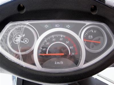 Common Instrument Function Description Power indicator: indicates that the vehicle power is turned on. Battery voltage: Indicates the voltage of the battery with a light emitting diode or voltmeter. Undervoltage indication: Indicates whether the battery is below the normal use value. The following overcurrent indication: indicates that the current motor is running. The current exceeds the maximum continuous current that is allowed. Motor Current: Displays the size of the current the motor is running. Speed ​​indication Intelligent electric vehicle "1:1 power assist", "Electric", "Constant speed" Riding status Travel speed Current vehicle in motion Speed ​​(km/h)
The lamp indication indicates whether the headlights, the left and right turn lights, and the brake lights are in the working state. The accumulated mileage indicates the number of kilometer-hours that the electric car has traveled. The current mileage The kilometers that this time is energized. Travel time The time (in hours, minutes, and seconds) for this energization. )
Current temperature Ambient temperature currently used for installation and disassembly Note In general, pointer-type instruments have a low degree of integration, the circuit wiring is relatively simple, and the instrument circuitry does not depend on the controller circuit. The failure of mechanical instruments is mainly focused on the faulty assembly and disassembly of the lead or instrument head. The positive and negative poles of the power supply cannot be mistaken. Liquid crystal display instruments are best at digitizing accurate displays of various data, such as speed, battery voltage, and mileage. If it is related to the display driver software and microcontroller models, such instrument failure, can only replace the instrument assembly.
When disassembling the instrument panel, special attention is required. In general, it is necessary to understand the function of the lead by referring to its circuit principle, and pay attention to the color and position of the lead. The general instrument circuit is an open circuit, and the circuit generally integrates a horn circuit, a steering and a humming circuit, and forms a situation in which the high and low voltage circuits on the instrument panel are co-existed. When disassembling, it is necessary to remove the battery first. After connecting the leads, place all the switches in the “OFF†position. Use a multimeter to measure the absence of a short circuit before installing the battery.
Principle and Maintenance of Electric Vehicle Dashboard 1. Pointer Instrument 1. Structure and Principle This type of instrument contains: Accumulated driving kilometers through 6-digit dial display, vehicle speed indicator table indication (km/h), speed, battery voltage pointer The table indicates battery voltage (volt), headlight indication, left/right turn signal indication, etc.
The accumulated mileage meter is six "decimal" gear counters. The vehicle speed pointer table is a damping tachometer. They share a single revolution input signal to perform conversion by means of mechanical transmission to achieve their own indication function.
The voltage pointer table is an ordinary 50 volt DC voltage meter.
2. Fault detection and maintenance pointer instrumentation is relatively low integration, circuit wiring is relatively simple, the instrument circuit does not depend on the controller circuit, can work independently.
Failures of mechanical instruments are mainly lead or instrument head failures. When disassembling the meter, special attention should be paid to the fact that the positive and negative poles of the power supply cannot be mistaken. The flasher provides the steering lamp gap voltage so that the steering light bulb can flash. The pin mark B of the flasher housing indicates that the battery L represents the light and cannot be connected incorrectly.
Second, the liquid crystal instrument 1. Structure and principle Through the special Hall sensor switch signal, transmitted to the liquid crystal display instrument assembly on the microcontroller, the number of wheel revolutions per unit time count, can calculate the vehicle speed, on By multiplying the travel speed and the travel time, the accumulated mileage of the vehicle can be calculated.
Some brushless motor controllers use internal single-chip microcomputer as the decoding chip, which can calculate the speed and total mileage of the motor directly and send it to the liquid crystal display instrument. There is no single-chip microcomputer inside the liquid crystal display instrument assembly.
Liquid crystal display instrument is best at digitizing accurate display of various data (such as speed, battery voltage, mileage, riding time, ambient temperature, etc.), enabling operators to see precise values ​​at a glance, but this kind of instrument The disadvantage is that the resistance to sunlight and ultraviolet radiation is poor, and the environmental temperature requirements are high. Therefore, liquid crystal display instruments cannot be exposed to sunlight for a long time and can only be used at an ambient temperature of -10-40°C. Prolonged use under high or low temperature conditions will cause irreversible damage to the LCD screen, so that the LCD display value will be blurred until it cannot be displayed.
2. The circuit for fault detection and maintenance of such meters is complex and the failure rate is relatively high. Some liquid crystal instrument circuits can work independently without relying on the controller circuit. Some liquid crystal instruments must rely on the digital signals of the microcontroller inside the controller to work. Due to the type of software and MCU that are involved in the display driver, this instrument can only replace the instrument assembly if it fails. In emergencies, the leads of the turn and the handle can be fed directly to the controller.
Third, the light-emitting diode instrument 1. Structure and principle The light-emitting diode indicating instrument circuit belongs to the electronic circuit, and the vehicle lamp circuit separation.
LED simulations indicate high, medium, and low battery voltages and under voltage. Its accuracy is relatively high, and its price is cheap. Currently it is widely used in electric vehicle instrumentation.
2.. Fault detection and maintenance The signal acquisition and signal processing of the LED instrument adopt digital digital logic chip. The circuit does not depend on the controller circuit and can work independently. Some electric vehicle handles and brake signals are transmitted through the dashboard and then output to the controller. In emergencies, the leads of the turn and the handle can be fed directly to the controller.
IV. Intelligent display instrument 1. Structure and principle The intelligent display instrument must be matched with the corresponding intelligent controller. The status of the light-emitting diode on the instrument panel is controlled by the intelligent controller. The content of the display is relatively high, not only can show the high, medium, low and under voltage of the battery voltage, but also can show the riding mode of the whole vehicle. Intelligent electric vehicles generally have three riding modes: "1:1 assist", "electrical", and "fixed speed". The controller transmits the current vehicle status data to the driver chip of the meter circuit and dynamically refreshes and illuminates accordingly. Light emitting diodes.
Light-emitting diode intelligent display instruments have many display functions, simple wiring, and low price, and are currently used in the electric vehicle industry.
In addition to these normal display functions, its use with the controller can also display faults in the vehicle's electrical control components. When the smart dashboard is used for fault detection of the entire vehicle, the corresponding display meanings of the respective light emitting diodes are:
1 Each indicator light flashes 3 times, and the detection indicator light can work normally.
2 The sequence of the power indicator lights indicates the positional relationship between the energization of the three Hall elements and the motor magnet. When the motor is turned by hand, the three indicators light up sequentially. If the indicator is lit in the order of 100, 110, 111, 011, 001, and 000 (where 1 represents light and 0 represents extinction), the brushless motor is indicated. The phase angle is 60 degrees. If the indicator lights up in the order of 100, 110, 010, 011, 001, and 101, the phase angle of the brushless motor is 120 degrees.
3 Turn the handle slowly. The blinking frequency of the "undervoltage" indicator light corresponds to the rotation angle of the handlebar. Turning the handle in the original position, the indicator light does not flash; the greater the rotation angle of the turn handle, the faster the indicator light flashes, the signal of the turn signal is normal. If you do not have this correspondence, it may be damage to the turntable or poor wire contact.
4 When the smart mode conversion button is pressed, the "assist" indicator is on, indicating that the power off switch is active.
5 Pinch the left and right brake levers respectively, the "electric" indicator light is on, and the light is off when it is released.
6 Slowly turn the pedal wheel one revolution. The "fixed speed" indicator flashes 5 times to indicate that the booster sensor is working properly.
2. Fault Detection and Maintenance The display content of the intelligent display instrument panel depends on the controller's data signal. If the instrument panel fails, the instrument panel assembly should be replaced. In case of emergency repair, the turn and brake signals can be directly connected to the controller.
Fifth, instrument panel disassembly When the instrument panel is disassembled and assembled, we must pay attention to the color and position of each lead. Refer to the circuit principle of various instruments to understand the function of each lead. Because the meter circuit does not have a special sealed enclosure seal, it is an open circuit. The vast majority of meter circuits are also integrated with horn circuit, steering and buzz circuit, some instruments and transition circuits of various lamps. The voltage of these circuits is generally 24V or 36V of the battery pack, but the display signal of the meter Circuit voltage is generally 15V circuit below, so that in the display instrument panel on the formation of high and low voltage circuits coexist, and instrumentation circuit is often the convergence of various leads, so the disassembly process, be sure to remove the battery, etc. After all kinds of leads, all the switches are all placed in the "OFF" position, and the diodes of the multimeter are used to measure +36V, +15V, +12V, and ground. After measuring no short circuit, the battery can be charged.
6. Substitution of instrument panel Since electric vehicles use the limited energy of vehicle batteries, their common feature is the display of battery voltage, and they are generally separated from control signals such as turning handles and brake handles. Therefore, in an emergency situation, we only need to detect the positive and negative battery wiring of the instrument circuit, +15V, +12V, and +5V ground wire, and connect these wires to each other, and then we can replace the instrument and complete the basic display. Functional.
Electric vehicle instrument panel disassembly and maintenance method