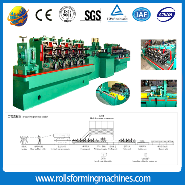
Welded Tube Mill is called cold Roll Forming Machine for welded pipe. Checking from the name, we can know that it is a kind of pipe making production line. For this machine, it supports the material thickness from 0.5-5mm, for diameter range from 10-127mm. And now there are four types welded pipe machines: HG32, HG50, HG76 and HG127. For different material thickness, diameter range, choose different pipe machine.Except them,we also supply Down Pipe Bender.
High Frequency Welding Tube Mill, Welded Pipe Mill, Tube Welded Machine,Down Pipe Bender Zhongtuo Roll Forming Machinery Co., ltd , http://www.rollsformingmachines.com
The contact occurs when the contact node K penetrates into the target surface defined by the target nodes i, j. The permeability is represented by the gap g. The gap value g has a certain correspondence with the normal force fn of the contact portion. There are two effective methods to deal with this correspondence: the penalty function method and the enhanced Lagrangian multiplication. Sub-law. The penalty function method contact force fn is approximated by the contact stiffness as: fnKngn when g<0 when 0 is g>0 (3) where the Kn contact stiffness is enhanced by the Lagrangian multiplier method, the contact gap can be generated by adding The Lagrange multiplier controls the size.
The magnitude of the contact force fn is expressed as: fnmin(0, Kngn i 1), where i 1 is the Lagrangian multiplier force in the i-th iteration step: i 1i Kngn(gn)i(gn<)(4) The personally defined compatibility gap limits the internal calculation factor, <1 the friction of the contact surface, ie the tangential force of the contact surface, is due to the increased friction of the contact nodes as they meet and move along the target. For the three friction forms (no friction, adhesive friction and sliding friction) is expressed as: fs0 frictionless KtuesKtgt
Finite element modeling gear, rack geometry parameters: gear teeth number Z14, gear module m45mm, gear displacement coefficient X0.5, gear tooth width B470mm. Single-section rack length is 5938mm. Material and allowable stress: select rack The material is 42CrMo4V (high frequency hardening) and the gear material is 17CrNiMo6 (surface hardened), the allowable stress of the two materials, as shown.
The adjustment plate, gear and rack are all made of SOLID92 unit, the embedded part embedded in the concrete is SHELL63 unit, and the concrete is made of SOLID45 unit. The two contact surfaces of the gear and the rack are defined as contact pairs. The enhanced Lagrangian multiplier method is adopted. Considering the friction and ambient temperature, the nonlinear calculation is carried out by the enhanced Lagrangian multiplier method. 1 thread contact stress and Vonmises stress, Vonmises stress and deformation of concrete and frame before and after temperature change. Since the matrix system considering the contact problem of friction is asymmetrical, and the sparse matrix solver is very effective for the non-positive definite problem and the Lagrangian multiplier problem, the sparse matrix solver is used for solving.
The root of the stressed tooth considers the transition fillet. The total number of units is 101,007, and the total number of nodes is 73,424. Cut off the upper and lower displacements in the X, Y, and Z directions, and constrain the Z displacement of the adjustment frame and the concrete side as shown. The calculation results of the finite element model of the rack and pinion are only subjected to static load: (1) The maximum contact stress of the gear tooth surface is 422 MPa. As shown, the maximum bending stress of the gear is 128 MPa. (2) The maximum Vonmises stress of the gear is 332 MPa. It is shown that the root Vonmises is 110 MPa. The comparison of the various parts of the mechanism before and after the temperature load is as shown.
The conclusion shows that the temperature load has little effect on the stress of the rack and pinion mechanism, and the local stress is reduced by mutual cancellation. The Y-direction displacement of the rack is 0.0050.7492mm. The Vonmises stress of the embedded part is 113.454MPa.

Analysis of Fluidization Operation of Large Frame Lifting Gear Structure Climbing Equipment