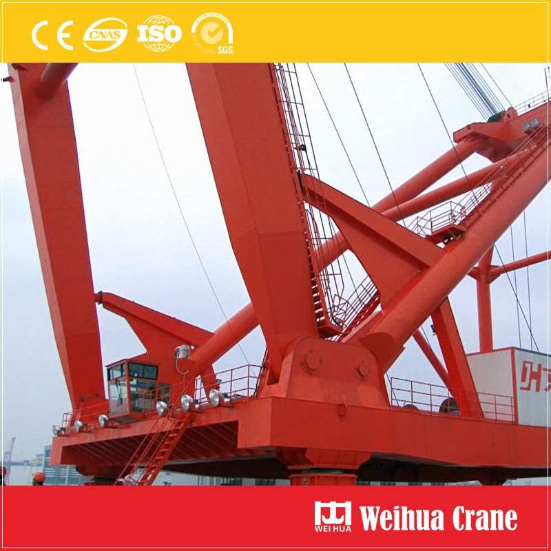
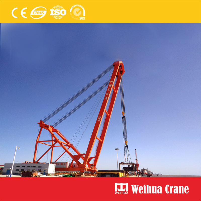
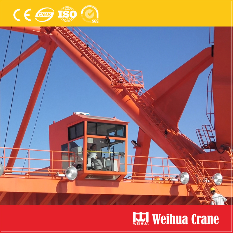
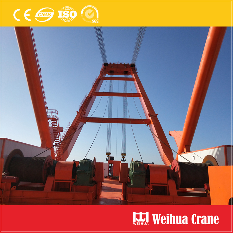
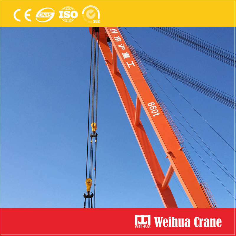
A Derrick Crane is docking equipment installed on vessels or dockside. Derrick crane consists of derrick and hoisting mechanism. There are 3 or 4 steel wires connecting the derrick and hoisting mechanism, which controls hoisting mast goes up and down. A separate steel wire sling runs under the hoisting mast with a hook as the hoisting mechanism.
Features of Weihua Derrick Crane:
1. There are 4 driving system for the hoisting mechanism, 2 driving system for luffing mechanism.
2. The whole derrick crane chassis adopt basin support on concrete foundation, which can effectively ease the horizontal and vertical deformation of the derrick crane.
3. Multi-layer winding line reel drum. Hoisting winding drum wrapped with 4 layers of wire rope, and luffing drum is wrapped with 5 layers of wire rope.
4. Complete frequency control, half load lifting speed is 2 times faster than the full load lifting speed.
5. Inverter, encoder and electronic control system to ensure the 4 hoisting motors keep synchronous working.
Weihua provide professional lifting equipment solutions, customized cranes, Crane Components, installation, after sale service. Weihua products export to 110 countries such as Russia, Thailand, Malaysia, Egypt, Saudi Arabia, Parkistan, the Philippines, Mexico, etc. We have confidence to provide you with the professional solutions and right products. Our success comes from customers' success. Welcome to visit Weihua.
Derrick Crane Derrick Crane,Fixed Derrick Crane,Fixed Dock Crane,Self-Climb Crane Henan Weihua Heavy Machinery Co., Ltd. , https://www.weihuacranefactory.com
Application of hydraulic control valve in building water supply
Hydraulic control valve is composed of a main valve and its external needle valve and pilot valve. Hydraulic control valve is a general term for a series of multi-purpose control and safety valves. Mainly include: 1) remote control float valve; 20 pressure reducing valve; 30 slow closing check valve; 40 pressure relief valve; 50 holding pressure valve and so on. Their main features are: the use of media in the mode of action their own pressure and hydraulic system operation, and automatic control, accurate action, performance *, can be widely used in life production and fire control system for water supply pipe play a role in control and safety. However, the hydraulic control valve in the project, there are still some errors, such as the valve conditions, valve design requirements, installation points, for this reason, this paper to CECS standard "hydraulic control valve application design rules" Draft) as the basis, combined with my experience to elaborate on the various aspects of the problem. 1, hydraulic control valve design points (1) engineering application of the hydraulic control valve is tested by the manufacturer, all kinds of labels complete, technical information to meet the requirements of the product. (2) According to the functional requirements, select the type of valve, and then determine the valve body and sealing parts of the valve according to the pipeline transportation media, temperature, building standards and the main requirements of the owners. Common body materials are cast iron, copper and iron, copper, plastic and so on. Common sealing surface and lining materials are copper alloy, plastic, steel, hard alloy, rubber and so on. Valve body material should be matched with the pipe material. (3) The nominal pressure of the valve is 0.6, 1.0, 1.6, 2.5 and 4.0MPa and other different levels, pipeline transport medium, the working pressure should be less than the nominal valve pressure value. (4) The hydraulic control valve in the project should be provided with enough space for management, operation, installation and maintenance, and should meet the requirements of the pipeline on the valve. (5) When the pipe is flanged, a flanged hydraulic control valve should be used. When the pipe is grooved, a grooved hydraulic control valve should be used. (6) Hydraulic control valve should be set in the medium flow of one-way pipeline. (7) The direction of the arrow on the main valve body of the hydraulic control valve must be consistent with that of the piping system. (8) then the hydraulic control valve pipe should not be blocked, gas resistance phenomenon. The highest position in the pipe network should be set automatically save gas exhaust valve. (9) When the valve is installed horizontally, the bonnet and stem should face upward. Vertical installation, the valve cover, stem should be outward. (10) The valve should be installed before the intensity and tightness test. (11) The strength and tightness of the valve shall meet the following requirements. A, the valve strength test pressure of 1.5 times the nominal pressure; B, valve tightness test pressure of 1.5 times the nominal pressure; C, the test pressure should remain unchanged during the test duration, and the shell packing and valve seal No leakage; D, valve test duration according to the above table. Valve test duration Nominal diameter DN (mm) Minimum test duration (S) Tightness test Strength test Metal seal Nonmetallic seal ≤ 50 15 15 15 65 ~ 200 30 15 60 250 ~ 450 60 30 180 2, remote control float valve (1) A liquid level automatic control valve, the use of the control loop float valve open and magnetic closure to control the opening and closing of the main valve, so as to achieve the set level control valve (2) remote control float group should be The following components (along the flow direction) A, control valve (gate valve or butterfly valve); B, filter; C, remote control float valve. Note: A, if the medium is cleaner, the main valve catheter system can be replaced with micro-filter pipe filter. B, the installation site, there should be disassembled filter space. (3) The remote control float valve shall be provided when the nominal diameter of the water inlet pipe of the living, production or fire-fighting water supply system (tank) is greater than or equal to 50mm. (4) The nominal diameter of the remote control float should be the same as the nominal diameter of the pipeline. (5) Remote control float valve should be set before the filter, the filter should meet the following requirements: A, the filter material should have sufficient strength and rigidity, should be made of stainless steel and copper; the total area of ​​the filter orifice flow should be pipe cross-sectional area Of 1.5 to 2 times the number of holes should be 20 to 60 mesh. B, should be easy to clean. (6) Remote control float valve should be installed in the pool or tank inlet pipe, should be installed horizontally, valve cover up. The control catheter and float set Qing meet the following requirements: A, remote control float valve control catheter should be fully fixed in the pool or tank, the total length of the control catheter should be more than 8cm, the float center should be 1cm away from the inlet or inlet should be Take wave device. B, within the same pool or tank above the overflow water level should be to prevent backflow pollution damage siphon phenomenon vent hole diameter 10mm, hole center and overflow water level should meet the following requirements. Ventilation center Distance from overflow water level (mm) Nominal diameter of pipe DN Ventilation center distance Overflow water level Height 50 100 65 100 (8) Remote control float valve outlet pipe in the basin Or water tank should be submerged outflow way to reduce the flow of noise, the nozzle should be below the minimum water level, but away from the pool or tank should be not less than 50mm. (9) remote control float valve * tank or tank wall installation. (10) When the outlet pipe of the remote control float valve is a metal pipe or a composite pipe, anticorrosive measures shall be taken on the outer wall of the inner pipe of the tank or water tank. 3, adjustable pressure reducing valve (1) can reduce the pressure and static pressure, and the valve medium before passing to the valve, and the valve pressure within a certain range of freely adjustable valve. According to the structure type can be divided into direct-driven direct relief valve and the pilot-equipped pilot pressure reducing valve. (2) the composition of the adjustable valve (along the flow direction) A, control valve; B, filter; C, pressure gauge before and after the valve; D, adjustable pressure reducing valve; E, flexible rubber joints or pipes Scaler; F, control valve. Note: A. When the main valve body of the adjustable pressure reducing valve is equipped with a pressure gauge, the pressure reducing valve group may not be equipped with a pressure gauge. B, when the main valve body with adjustable pressure reducing valve with its own filter device, the pressure reducing valve group may not set a filter. C, the installation site should remove the filter device space. (3) Water supply and hot water supply systems for life, production, firefighting shall be fitted with water supply pressure relief valves where static pressure reduction is required and the following conditions are met: A. High-rise buildings need to be subdivided into zones without water supply When decompression tank; B, when required by the static pressure; C, water point or fire water supply facilities require water pressure stability. (4) valve should be set to two groups, one of the spare. (5) The setting of the pressure reducing valve is convenient for management, operation, installation and maintenance; the pressure reducing valve should not be installed in the ceiling or residential door; and enough space should be reserved when the pressure reducing valve is installed in the pipe well. (6) pressure relief valve should be set in the one-way flow of the pipeline. (7) The selection of adjustable pressure reducing valve shall meet the following requirements: A. The diameter of pressure reducing valve shall be selected according to the product flow-head loss curve of the product; B. The pressure rating of adjustable pressure reducing valve shall be high Before the scheduled valve pressure value; C, adjustable valve after the highest pressure and the lowest pressure should comply with the following table. (MPa) Item Pressure rating 1.0 1.6 2.5 The highest pressure before the valve 1.0 1.6 2.5 The highest pressure after the valve 0.8 1.0 1.0 The lowest pressure after the valve 0.05 0.05 0.05 D, the minimum pressure before the valve should be greater than the dynamic pressure after the valve 0.2MPa; E, domestic water supply system Adjustable pressure reducing valve, the maximum pressure difference between the valve before and after the valve is not more than 0.4 MPa; In places with quiet requirements (residential, hotels, hospitals) Water supply system Adjustable pressure reducing valve before the valve and the maximum pressure difference Greater than 0.3 MPa. When the life of the water supply system before the valve and the valve after the maximum pressure difference exceeds the above provisions, adjustable pressure relief valve should be set in series or take anti-noise measures. (8) When the adjustable valve nominal diameter of not more than 50mm, the linear pressure reducing valve should be used; when more than 50mm less than 100mm, it is advisable to use pilot-operated pressure reducing valve. (9) In some high-rise civil buildings with extremely uneven water consumption (such as hotels, residences and hospitals), adjustable pressure relief valves should be installed in different diameters in parallel when there is quiet demand. Diameter should be set in parallel with the following requirements; A, according to the main and auxiliary pressure reducing valve working conditions and flow characteristics to determine the main and auxiliary reducing valve diameter. Generally, the auxiliary pressure reducing valve should be two or more than the nominal diameter of the main reducing valve; B, the pressure after the auxiliary reducing valve should be higher than the pressure after the valve of the main reducing valve by 00.020 ~ 0.035 MPa (dynamic pressure value) . Note: A. When the different diameters are set in parallel, the design flow through should be calculated according to different nominal diameter or adjustable pressure reducing valve at the same time. B, Reducing the parallel set only applies to adjustable pressure reducing valve. C, the main valve for the direct relief valve, the auxiliary valve may not be parallel. D, Reducing the parallel set, the main valve can be no longer with the diameter reducing valve. (10) Adjustable pressure reducing valve should be installed horizontally. When installed horizontally, the bonnet should be upward. (11) After the valve of the fire water supply system, there should be drainage facilities. (12) When the automatic sprinkler system needs depressurization, the pressure reducing valve should be installed in front of the alarm valve (along the flow direction), with a single alarm valve supporting the set pressure reducing valve, not equipment with pressure reducing valve; and multiple Valve supporting the establishment of the valve, the valve should be used plant equipment. (13) for the hot water supply valve, should be used hot water valve. (14) The hot water supply project with dry-pipe circulation mode (semi-circulation mode) should be used. The requirements for setting the pressure reducing valve should be the same as that of cold water project. The hot water supply project with vertical circulation mode (full circulation mode) The valve should be set to prevent the destruction of hot water circulation, the district back to the pressure at the convergence point should be balanced. 4, slow closing check valve (1) the use of medium pressure control and delay off to achieve to eliminate or alleviate the water hammer check valve. (2) slow-closing check valve assembly of the following components (along the water flow direction); A, pressure gauge; B, flexible rubber joints or pipe expansion device; C transitional device; Valve; E, control valve (gate valve or butterfly valve). Note: A, slow-closing check valve body itself is equipped with a pressure gauge, pressure gauge can no longer be set. B, the filter settings are difficult, you can not install. (3) Life, production, fire water supply system, the need to stop the pump back to stop the media back and eliminate or alleviate the resulting water hammer phenomenon, should set the slow-closing check valve. (4) slow-closing check valve should be set in the outlet section of the pump, should be installed horizontally, valve cover up. When mounted vertically, the bonnet should be facing outward. (5) A pump unit shall be provided with a set of slow-closing check valve sets. (6) The nominal diameter of the slow-release check valve shall be the same as the nominal diameter of the pipeline. (7) Rinse the pipe before installation. (8) The best installation orientation is vertical, the other azimuth can be. (9) confirm the system conditions. Pressure, caliber, medium, medium temperature, flow. Reasonable choice slow closing check valve specifications. (10) to maintain the valve cavity cleaning. (11) In the medium contains more debris, the filter should be more within the device net, in order to maintain the safe operation of the valve. 5, relief valve, holding pressure valve (1) a pressure control valve, it does not use any external force but the use of media pressure to open or close. Valve opening pressure can be adjusted within a certain range, when the pressure is restored to set the following ground, the valve automatically shut down to prevent the media following the discharge. (2) The valve used in pipelines, can quickly respond to pressure waves and rapid release, to prevent the pressure increased sharply damaged pipelines and equipment, especially for high-rise building fire protection system pressure relief; and can be used to maintain a constant pressure on the water supply upstream of the main valve . A, life, production, fire water system need to maintain pipeline pressure within a certain range (such as 1.0 Mpa) to prevent sudden pressure rise and eliminate the gradual increase due to flow changes pressure is too high to cause harm to the pipeline should be set vent Pressure valve. B, life, production of water supply pipeline, the need to maintain a certain region of the pipeline pressure in a specified range of values, should be set holding pressure valve. (3) relief valve group should be composed of the following components (along the flow direction); A, pressure gauge; B, control valve (gate valve or butterfly valve); C, filter; Note: A, relief valve body itself is equipped with a pressure gauge, pressure relief valve group can no longer set pressure gauge. B, such as medium is more clean, available pressure relief valve catheter system micro-filter instead of pipe filters. C, the installation site, there should be disassembly of the filter device space. (4) The relief valve shall be located at the front of the piping system in the protected area and shall be located after the piping system check valve (in the direction of water flow). In order to prevent the pump overpressure and pump overpressure water pressure relief valve set up should be located in the pump room. (5) Pressure relief valve should be installed in parallel with the piping system drain pipe, and should be installed horizontally, valve cover up. (6) Pressure relief valve connected to the outlet pipe, its diameter should not be reduced. (7) The same system of two or more than two pump units can share pressure relief valve. (8) The outlet of the relief valve should have pollution prevention measures and energy dissipation devices to prevent the back of Beijing opera. (9) The holding pressure valve assembly shall consist of the following components (along the flow direction): A, pressure gauge; B, control valve (gate valve or butterfly valve); C, filter; D, pressure holding valve; Or butterfly valve) Note: A, holding pressure valve main body itself with a pressure gauge, pressure holding valve group can no longer set pressure gauge. B, the filter should have a displacement compensation device. C, the installation site, there should be disassembly of the filter device space. (10) holding pressure valve can be set in the main pipe or branch pipe should be set in tandem to set the most end area of ​​the packing area. And should be installed horizontally, valve cover up. (11) For important pipelines, pressure-holding valves shall be set in parallel with one prepared for use. (12) The pressure pipe connecting the outlet end of the pipe should not be reduced. (13) holding pressure valve outlet pipe section can be set pressure gauge. (14) When the nominal pipe diameter is less than 200mm, the nominal diameter of the pressure relief valve shall be the same as or smaller than the nominal pipe diameter; when the pipe nominal diameter is greater than or equal to 200mm, the nominal diameter of the pressure relief valve shall be adopted 150mm. (15) Pressure exchange valve with the public path should be the same nominal diameter of protected pipelines. (16) Relieve pressure Relief, pressure holding valve pressure level should be based on water supply (including fire) system to determine the working pressure. Usually should be with the water (including fire) pump outlet pipe pressure level on the same. (17) If the pressure relief valve drain farther position, the drainage pipe is too long (> 20m), drainage pipe diameter than the pressure relief valve before the pipe network pressure stability. (18) Fire-fighting water supply system During the pressure test, if the system test pressure is higher than the nominal pressure of the selected relief valve, the shut-off valve in front of the relief valve should be closed to prevent the relief valve from being damaged or malfunctioning. (19) pressure relief valve system should be closed. (20) Relieve pressure Relieve pressure, holding pressure valve set high pressure to open the pressure Ps see the table below. (MPa) Item Pressure rating 1.0 1.6 2.5 The highest pressure before the valve 1.0 1.6 2.5 The maximum setting opening pressure Ps max 0.9 1.4 2.0 Note: PS value should not be set too low, otherwise it is easy to release pressure. 6, the hydraulic control valve changes in the case of the main valve unchanged, through the needle valve, pilot valve and the corresponding control system, according to different requirements in the pipe network, can evolve dozens of kinds of functions of the valve, in addition to the above 5 Commonly used outside the water supply system there are electric float valve, hydraulic electric control valve, electromagnetic control valve, flow control valve, emergency shut-off valve. There are different design requirements and installation requirements. 7.Conclusion (1) Hydraulic control valve is widely used in building water supply system (including fire control system) due to its use of medium pressure and hydraulic system operation, automatic control, accurate operation and performance. (2) Introduced the remote control float valve, adjustable pressure relief valve, slow closing check valve, pressure relief valve and holding valve several commonly used hydraulic control valve design selection and installation points. (3) Hydraulic control valve Like many other valves, there are many functions that we need to know and develop, such as the development of small-caliber flow control valve, the requirements of rubber for various hydraulic control valve, the life of spring, In order to be better applied to the project.