Torque sensors (also known as torque sensors , torque sensors , torque sensors , torque instruments ) are divided into two major categories of dynamic and static, in which dynamic torque sensors can be called torque sensors, torque and speed sensors , non-contact torque sensors, rotation Torque sensors . Torque sensors are the detection of torsional moments on various rotating or non-rotating mechanical components. Torque sensors convert the physical changes in torque into precise electrical signals. Torque sensors can be used in the manufacture of viscometers, electric (pneumatic, hydraulic) torque wrenches, it has high precision, fast frequency response, good reliability, long life and other advantages. Torque is a parameter most frequently involved in a rotary power system. In order to detect the rotational torque, a twist angle phase difference sensor is often used. The sensor is equipped with two sets of gears with the same number of teeth, shapes and mounting angles at both ends of the elastic shaft. A proximity (magnetic or optical) sensor is mounted on the outer side of the gear. When the elastic axis rotates, the two groups of sensors can measure two sets of pulse waves. Comparing the phase difference between the front and rear edges of the two sets of pulse waves can calculate the amount of torque that the elastic shaft can bear. The advantages of this method are: non-contact transmission of the torque signal, digital signal detection signal; disadvantages: large size, difficult to install, low speed performance is not ideal because the front and rear edges of the pulse wave are relatively slow and difficult to compare. The mature test method for torque testing is strain gauge technology. It has the advantages of high precision, fast frequency response, good reliability, and long service life. The dedicated torsional strain gauge is glued on the elastic shaft to be measured with a strain gauge, and a strain bridge is formed. If the strain bridge is supplied with the working power, the elastic shaft can be tested for the torsion of the electrical signal. This is the basic torque sensor mode. However, in the rotary power transmission system, the most intractable problem is how the bridge pressure input and the detected strain signal output of the strain bridge on the rotating body are reliably transmitted between the rotating portion and the stationary portion. The usual practice is to use a conductive slide. Ring to complete. Since the conductive slip ring is a frictional contact, there is inevitably wear and heat generation, which limits the rotational speed of the rotary shaft and the service life of the conductive slip ring. And due to unreliable contact caused by signal fluctuations, resulting in large measurement errors or even unsuccessful measurements. In order to overcome the defect of the conductive slip ring, another method is to adopt a radio telemetry method: the torque strain signal is amplified on a rotary axis and is V/F converted into a frequency signal, and is transmitted from a rotary shaft by radio modulation by carrier modulation. To the outside of the axis, using the method of radio reception, you can get the twisted signal of the rotating shaft. The energy supply on the rotating shaft is a battery that is fixed on the rotating shaft. This method is a remote torque meter. Non-contact torque sensor Non-contact torque sensor The input shaft and the output shaft are connected by a torsion bar. The input shaft has splines and the output shaft has a keyway. When the torsion bar is twisted by the rotational torque of the steering wheel, the relative position between the spline on the input shaft and the keyway on the output shaft is changed. The relative displacement of the spline and the keyway is equal to the amount of torsion of the torsion bar, so that the intensity of magnetic induction on the spline changes, and the change in magnetic induction strength is converted into a voltage signal by the coil. Non-contact torque sensors have been used in a non-contact mode of operation, so they have a long life, high reliability, are less susceptible to wear, have a smaller delay, are less affected by shaft deflection and axial misalignment and have been widely used. Car field. [1] Strain gauge torque sensor Strain gauge sensor torque measurement using strain gauge technology. A strain gage is attached to the elastic shaft to form a measuring bridge. When the elastic shaft is slightly deformed by the torque, the resistance value of the bridge is changed, and the change of the resistance of the strained bridge is converted into a change of the electric signal to realize the torque measurement. The sensor completes the following information conversion; the sensor consists of a flexible shaft, a measuring bridge, an instrumentation amplifier, and an interface circuit. High-performance wireless torque sensors combine sensors and wireless communication technologies to achieve wireless data transmission. After the torque electric signal is amplified by the signal processing circuit controlled by the single-chip microcomputer and A/D converted, the encoder transmits the collected digital code to the transmitting module for transmission. After the receiving module receives the data, the decoder transmits the decoded data to the microcontroller and displays the obtained torque data value by the LED. Sensor data acquisition and transmission circuit consists of torque sensor, signal processing part, single-chip microcomputer and wireless transmitter circuit. The torque sensor transmits the strained electrical signals generated by the strain gauges to the signal processing circuit. The signal processing section extracts and amplifies the analog signal from the sensor and performs analog-to-digital conversion. The microprocessor is responsible for controlling the operation of all parts of the system and processing digital signals. Under the control of the microprocessor, the wireless transmitter circuit encodes and processes the information data collected by the encoder and transmits it with the transmitter module. Realize wireless transmission. Electronic Torque Meter is a portable, high performance shaft power measurement instrument for wind turbine, water pump testing and on-site energy efficiency evaluation. The electronic torque meter creatively eliminates the cumbersome and complicated installation process of traditional electromechanical torque sensors and is difficult to implement in many field environments, realizing the real-time measurement of the efficiency of fans and pump motors, and monitoring all aspects of the fan and water pump motors during use. The operating status provides real-time, real, and reliable data for studying the use status of fans and pump motors; it avoids the influence of improper installation of electromechanical torque sensors on the test results. The electronic torque meter can completely replace the shaft power measurement function of the traditional torque sensor, and can obtain the real-time efficiency of the fan and the pump motor, providing a rigorous, scientific evaluation means for the fan, pump unit energy-saving. The torque sensor is a precision measuring instrument that measures various torques, speeds, and mechanical power. The application range is very wide, mainly for: 1. Detection of output torque and power of rotating power equipment such as motors, engines, and internal combustion engines; 2, the fan, water pump, gear box, torque wrench torque and power detection; 3. Detection of torque and power in railway locomotives, automobiles, tractors, aircraft, ships, and mining machinery; 4, can be used to detect the torque and power in the sewage treatment system; 5, can be used to manufacture viscometer; 6, can be used in process industry and process industry; 7, can be applied to laboratories, testing departments and production monitoring and quality control; Torque measurement: Strain gauge electrical measurement technology is used to form a strain bridge on the elastic shaft. As shown in Figure 1: 1. The signal output can be arbitrarily selected waveform - square wave or pulse wave. 2 high detection accuracy, good stability, strong anti-interference. 3. No need to repeatedly zero; continuous measurement of positive and negative torque. 4. The static torque can be measured, and the dynamic torque can also be measured. 5. The small size and heavy sensor can be used independently from the secondary instrument. Just press the socket pin number to provide +15V, -15V (200mA) power, and then output square wave or pulse wave frequency signal with impedance proportional to torque. Lightweight and easy to install. 6. Measurement range: 0-10000Nm standard optional, non-standard 20,000Nm, 30,000Nm, 50,000Nm, 80,000Nm, 100,000Nm, special range can be customized. Square wave signal, pulse signal. · The standard signal output of the torque sensor is the frequency signal, ie 5-15KHz; in order to meet customer needs, no external module is needed, and the integrated output with the original output circuit directly outputs 4-20mA, 0-20mA, 1-5V, 0-5V analog Signal, convenient for customers. 2, torque signal processing form: · The frequency signal output from the torque sensor is sent to a frequency meter or a digital meter, and a frequency signal or a voltage or current signal proportional to the torque is directly read. · The torque and frequency signals of the torque sensor are sent to the secondary device of the SCM. The real-time torque value, speed and output power value and RS232 communication signal are directly displayed. · Directly send torque and speed frequency signals to a computer or PLD for processing. [1] Frequency output signal signal acquisition frequency signal output, and the following signal acquisition device recommended interface circuit as shown Current or voltage output signal acquisition as shown. 1. When installing, do not operate with electricity. Don't knock and bump the sensor directly. 2. The fastening bolts of the coupling should be tightened. The outside of the coupling should be equipped with a protective cover to avoid personal injury. 3. The signal line output must not be earthed, and the power supply must be short-circuited. The output current should not exceed 10 mA. The shielding of the shielded cable must be connected to the common terminal (power ground) of the +15 V power supply. The torque sensor should be installed in an environment with an ambient temperature of 0°C to 60°C, a relative humidity of less than 90%, and no flammable or explosive materials. Should not be installed in a strong electromagnetic interference environment. (1) Horizontal installation: as shown in Figure 11: (2) Vertical installation: Figure 12 shows: 3, connection: connection between torque sensor and power equipment, load equipment (1) The connection of the elastic pin coupling is shown in Fig. 13. This type of connection is simple in structure, easy to process and easy to maintain. It can compensate the relative displacement of the shaft caused by installation errors in a slight amount, and it can also play a minor role in vibration reduction. Suitable for medium-load, high-speed operation with frequent start-ups, operating temperature is -20-70°C. (2) Rigid Couplings Connections As shown in Figure 14, this type of connection has a simple structure, low cost, no compensation, no damping, and high precision in the installation of two axes. For very low vibration conditions. 4, installation requirements: (1) The torque sensor can be mounted horizontally or vertically. (2) As shown in Figures 11 and 12, the power equipment, sensors, and load equipment should be installed on a stable foundation to avoid excessive vibration. Otherwise, data instability, measurement accuracy, or even sensor damage may occur. (3) Use a flexible pin coupling or a rigid coupling. (4) The concentricity of the axes of power equipment, sensors, and load equipment should be less than Φ0.05mm. With the continuous improvement and development of the automatic control system, higher requirements are placed on the accuracy, reliability and response speed of the torque sensor. The torque sensor is showing the following trends: 1. The test system develops in the direction of miniaturization, digitization, intelligence, virtualization, and networking; 2. From single-function to multi-function development, including self-compensation, self-correction, self-adaptation, self-diagnosis, remote setting, state combination, information storage and memory; 3, to the direction of miniaturization and integration. The detection part of the sensor can be miniaturized through the rational design and optimization of the structure. The IC part can integrate as many semiconductor parts and resistors as possible into a single IC part, reducing the number of external parts; 4, from static testing to dynamic online detection direction; The success of the remote-measuring torque meter lies in overcoming the two shortcomings of the electric slip ring, but there are also three shortcomings. One is that it is susceptible to interference from the use of on-site electromagnetic waves; Second, because it is battery-powered, it can only be used in the short term; Thirdly, due to the additional structure on the rotating shaft, it is easy to cause the problem of dynamic balance at high rotation speed, which is more prominent in small-range and small-diameter shafts; The digital torque sensor draws on the advantages of the above methods and overcomes its drawbacks. Two sets of rotary transformers have been designed on the basis of strain sensors, enabling non-contact transfer of energy and signals. And has done the transmission of the torque signal has nothing to do with the rotation, has nothing to do with the magnitude of the speed, has nothing to do with the direction of rotation. 1. Torque sensor signal output and signal processing correction  . Sensor [Reference date 2013-05-04] The water tank radiator, the main product structure is the tube fin and the plate fin structure, the water flows through the tube, and the heat is transferred to the tube and the fin to realize the cooling of the high temperature water.
Application: At present, the products are widely used in various agricultural machinery such as automobile radiators, buses, trucks, special vehicles, road maintenance vehicles, generator sets, tractors, etc.
Water Radiator,Central Heating Radiators,Heating Radiator,Electric Radiator Heater Xinxiang Zhenhua Radiator Co., Ltd. , https://www.thermictransfer.nl
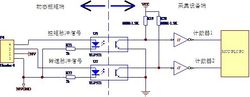 Frequency signal acquisition
 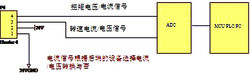 Current and voltage signal acquisition


Advantages: The product structure is simple, can be customized to Chengdu high, light weight, low cost and so on.

Torque sensor
The torque sensor I have a new statement
1 Introduction
Reference materials