Variable Frequency Screw Air Compressor Screw Type Air Compressor,Variable Frequency Screw Compressor,Variable Frequency Screw Air Compressor,Variable Frequency Screw Type Air Compressor Ningbo Xinda Screw Compressor Co., Ltd. , https://www.augustcompressor.com
In the 1980s, based on the principle of early-range traveling wave fault location in Type A at home and abroad, the principle of traveling wave distance protection integrating protection and ranging was proposed [2, 3]. However, due to the unreliability of ranging algorithms and the limitations of on-site test conditions, traveling wave distance protection has not been further developed.
In the 1990s, China proposed the principle, algorithm and implementation scheme of traveling wave fault location for transmission lines using current transient components[4-8], which promoted the development of modern traveling wave fault location (MTWFL) technology[ 9], and successively developed a modern traveling wave fault location device and system that incorporates multiple principles such as A, D, and E. The absolute ranging error has been able to reach within 200m [10,11]. In the field of applied research, in order to further improve the accuracy of traveling wave fault location, the wavelet modulus maximum detection theory has been more and more widely used in single-end and double-end traveling wave fault location [12-15].
In recent years, domestic scholars have begun to use A-type modern traveling wave fault location principle for relay protection, and proposed a distance-based traveling distance protection principle based on wavelet transform [16,17].
In order to better use the A-type modern traveling wave fault location principle for measured waveform analysis, this paper divides it into three independent operating modes, namely standard mode, extended mode and integrated mode, and gives each of them for actual measurement. A typical example of current transient waveform analysis.
1. Operation mode of A-type modern traveling wave fault location principle The modern A trip type ranging principle is single-ended principle. According to the different nature of the reflected wave detected, the A-type modern traveling wave ranging principle can be divided into three kinds of operating modes, namely standard mode, extended mode and integrated mode. In the standard mode, the reflected wave at the fault point needs to be detected. In the extended mode, the reflected wave at the opposite bus bar needs to be detected. In the integrated mode, the second reverse wave surge needs to be detected and the nature thereof is identified.
1.1 Standard mode A modern modern traveling wave fault location principle in the standard mode utilizes the time delay between the first positive line surge sensed at the measurement end on the line fault and its reflected wave at the fault point to calculate the measurement point. The basic principle of the distance between fault points is the same as that of the early A-type traveling wave fault location. In order to implement the modern traveling wave fault location principle of Type A in the standard mode, it is necessary to be able to accurately and reliably detect the first forward wave caused by the fault wave reflected at the fault point at the measurement end.
1.2 Extended mode A-type modern traveling wave fault location principle in extended mode utilizes the first reverse row wave surge experienced at the measurement end in the line fault and the initial fault wave transmitted through the fault point in the pair Time delay between the reflected waves at the end bus The distance between the end bus to the fault point is calculated.
In order to realize the A-type modern traveling wave fault location principle in the extended mode, it must be able to accurately and reliably detect the reflected wave of the initial fault wave transmitted by the fault point on the opposite busbar at the measurement end.
When the reflection point of the transient wave of the fault point is small, the reflected wave of the first forward wave of the local wave may not be detected at the measurement end, resulting in the A-type modern traveling wave in the standard mode. Fault location principle fails. However, in this case, the A-type modern traveling wave fault location principle under extended mode can work well.
1.3 Mode A modern traveling wave fault location principle in the integrated mode Utilizes the time delay between the first forward line surge and the second reverse line surge sensed at the measurement end when the line is faulty. Calculate the distance between the local measuring point or the opposite bus to the fault point.
The analysis shows that regardless of the bus connection mode, the reflected waves with more obvious amplitude can be generated when the fault initial wave surge arrives at the bus bar [4]. It can be seen that when the line fails, the time at which the measurement end senses the first forward wave surge and the first reverse wave surge is the same. The second reverse wave surge sensed at the measuring end can be either the first forward wave, the reflected wave at the fault point (when the fault point is within the midpoint of the line), or it can be the fault point. The transmitted initial wave of the initial fault wave is reflected from the opposite bus (when the fault point is outside the midpoint of the line), or it can be a superposition of the two (when the fault point is exactly at the midpoint of the line). For high-impedance faults (weak reflection waves at the fault point), even if the fault point is located within the midpoint of the line, the second reverse line surge sensed at the measurement point may also be the reflected wave at the opposite bus bar. For faults where the arc at the fault point is prematurely extinguished (reflected waves do not exist at the fault point), the second reverse wave surge felt at the measuring point is the reflected wave of the opposite bus regardless of the location of the fault point.
Therefore, when the line is faulty, single-ended traveling wave fault location can be achieved if the nature of the second reverse line surge is correctly identified at the measurement end. Specifically, when the second reverse wave oscillates as the first forward wave of the local reflected wave at the fault point, the time delay between the two corresponds to the local measurement point to the fault point. Distance between the two; when the second reverse wave is the reflected wave from the opposite bus, the time delay between it and the first forward wave of the local measurement point corresponds to the failure of the opposite bus. The distance between points.
It can be seen that in order to implement the A-type modern traveling wave fault location principle in the integrated mode, it is necessary to accurately and reliably detect the second reverse wave surge caused by the fault and identify its properties at the measurement end.
2. The direct waveform analysis method using current transient component to realize the principle of A type traveling wave distance measurement 2.1 Basic relationship of traveling wave fault location From the perspective of traveling wave fault location, the bus can be divided into two wiring types [4]. Among them, the first bus line is connected to multiple lines with the same voltage level, while the second bus line is connected to only one line. Most of the buses in the power system are Class 1 buses. With respect to the traveling wave from the direction of the line MN, the equivalent wave impedance of the measuring terminal bus M is equal to the parallel impedance of the wave impedance of all the lines except the line MN and the distributed capacitance of the busbar. Assuming that all the lines connected to the bus M have the same wave impedance, the time-domain reflection coefficient KMR and the time-domain transmission coefficient KMT of the transient transitional wave of the bus M from the direction of the line MN can be expressed as: 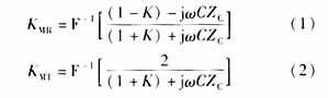
Where: F-1 represents the inverse Fourier transform; K is the number of lines connected to the bus M other than the line MN (assuming K ≥ 2); C is the distributed capacitance of the bus M; and ZC is the line impedance.
Assuming that the positive direction of the M-terminal current is the bus-to-line direction, the transient current fault component of the current caused by the initial line surge generated by the fault of the line MN to the local end can be expressed as: 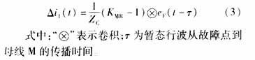
The first forward wave at the M end, wave eF(t) (ie, the wave reflected from the initial wave of the fault at the bus M), is the transient current component of the current caused by the reflected wave at the fault point reaching the bus M. It can be expressed as: ![]()
Where: KFR is the reflection coefficient of the voltage transient wave at the point of failure (assumed constant).
The transient current component of the current caused by the wave of the initial wave of the fault when the reflected wave of the bus N of the opposite line MN reaches the bus M through the fault point can be expressed as: 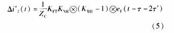
Where: KFT is the transmission coefficient of the voltage transient wave at the fault point (assumed constant); KNR is the reflection coefficient of the voltage transient wave at the opposite bus N; it is the transient travel wave from the fault point to the opposite bus. N propagation time. ![]()
Comparing equations (3) to (5) yields:
The reflection coefficient of the transient traveling wave at the bus M and fault point F is always negative, and the transmission coefficient at the fault point is always a positive value. Therefore, when the fault initial wave surge and the reflection wave at the fault point arrive at the bus M, the current transient fault components Δi1(t) and Δi2(t) of the line MN have the same polarity, and the time delay between them is equal to The travel time of the traveling wave between the measurement point and the fault point at the M end. The initial wave surge of the fault and its transient current component Δi1(t) and Δi′2(t) caused by the reflected wave of the opposite bus N of the opposite line to the M-side bus are within an initial period ( Dependent on the connection mode of the opposite bus N) has the opposite polarity [4], the delay between the two is equal to the travel time of the transient traveling wave between the fault point and the opposite bus N.
It can be seen that when the line fails, the reflected wave from the fault point and the line-to-end bus can be identified by comparing the initial polarity of the transient component of the line current caused by the line surge from the direction of the fault to the measuring terminal bus. In this case, as long as the current transient components of the line caused by the line surge from the fault line in the forward direction and the reverse direction to the measuring terminal bus can be correctly distinguished, the A-type modern line in various operating modes can be realized. Wave fault location principle.
2.2 Identification of current transient components caused by surges from the direction of the fault Line transients arising from the line surge at any point X in the direction of the fault and arriving at the bus M can be expressed as: 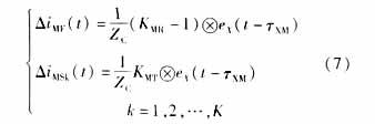
In the formula, it is the travel time of the transient traveling wave from X to the bus M; K is the number of adjacent sounding lines (set K≥2).
Since the reflection coefficient KMR is always less than 0, Equation (9) shows that the transient line current transient component caused by any row of waves from the fault direction arriving at the bus M and the transient components of all other adjacent sound line currents. There is a reverse polarity relationship.
Similarly, it can be seen that there is a reverse polarity relationship between the transient component of the line current caused by the row surge in the positive direction from any line to the bus M and the transient component of currents of all other lines (including the faulty line). Therefore, by comparing the polarity of each line current transient component caused when the wave surge arrives at the bus M, the current transient component caused by the wave surge from the fault direction can be identified.
When there are many outgoing lines on the bus, the amplitude of the current transient components of the sound lines caused by the line surge from the fault direction to the bus is small, and even negligible, thus simplifying the fault ranging process.
It should be pointed out that in the above analysis, the line loss and line frequency characteristics of the line parameters are not taken into consideration. These influencing factors will cause the attenuation and distortion of the traveling wave during the propagation process, but the polarity relationship between the above mentioned lines is still established. .
2.3 Implementation steps of the direct waveform analysis method The concrete steps for implementing the modern AWD fault location principle using the direct waveform analysis method of current transient components are as follows (in the case of the integrated mode):
1) Select the fault line by comparing the polarity of the first wave head component in the transient component waveforms of the current faults on the same bus.
2) For each wave head component in the fault line current transient waveform, determine the second wave head component caused by the wave surge from the fault direction by comparing its polarity with the other line current transient component at the same time;
3) Compare the initial polarity of the 2nd wave head component and the 1st wave head component in the transient current of the line current by comparing the faults caused by the wave surge from the fault direction. Determine the 2nd wave head component is the reflected wave from the fault point. Caused by the two (the same polarity), or caused by the reflection of the opposite bus bar (both reverse polarity), and then determine the location of the fault.
3. Measured fault analysis 3.1 Both the local and peer busses are Type 1 busbars. At 12:17:49 on December 14, 1997, the 330kV Hummer line (311km in length) governed by the Gansu Tianshui Power Supply Bureau was phased A. Ground faults, including the transient fault component waveforms of the faulty phase currents on the three lines with the faulty lines on the west side of the bus, are shown in Figure 1. Obviously, the local bus is the type 1 bus. In the faulty line, the second wave head component caused by the wave surge from the fault direction always has the opposite polarity to the initial wave head component, and therefore must be caused by the reflected wave of the opposite bus bar, and the first bus is also the first one. Class bus, which can be directly obtained in the extended and integrated mode of the ranging result is 75.8km, as shown in Figure 1 (a). The ranging result in the standard mode can be obtained indirectly (in this example, it is difficult to obtain it directly). It should be equal to the difference between the actual conductor length of the faulted line and the ranging result in the extended or integrated mode and can be approximated as (km). From the transient line current transient component waveforms, it can be found that there is no transient wave head component at the position corresponding to the approximate ranging result, but there is a wave from the fault direction at 235.6 km from the local end in its neighborhood. The transient wave head component caused by the surge is shown in Fig. 1(b), so that the ranging result in the standard mode can be corrected to 235.6 km. The actual fault point is located at (235-236) km from the local end. In this example, the reflected wave from the opposite bus arrives at the local measurement point before the reflected wave at the fault point, and therefore the fault point is located outside the midpoint of the line (close to the opposite end). 
At 14:33:7 on April 5, 2002, a phase B ground fault occurred on the 220kV Kanglanjia Line (64.3km in total length) under the jurisdiction of the Heilongjiang Suihua Power Bureau, including the faulty lines on the Kangjin side, on the same bus. The fault current waveforms of the faulty phase currents of the three lines are shown in Figure 2. There are multiple other lines connected to the busbars at both ends of the faulty line, so the busbars at both ends are Type 1 busbars. On the faulty line, the second wavehead component caused by the wave surge from the direction of the fault always has the same polarity as the initial wavehead component, and therefore must be caused by the reflected wave at the fault point, so that the standard and comprehensive modes can be directly obtained. The distance measurement result is 27.4 km, as shown in Fig. 2(a). On the faulty line, the 3rd wave head component (overlaid on the 2nd transient component of the transient waveform) from the direction of the fault wave always has the opposite polarity to the initial wave head component, so it must be The line-to-end bus reflected wave caused by the line, which can be directly obtained in the extended mode of the ranging result is 36.9km, as shown in Figure 2 (b) below. The actual fault point is located 37km away from the opposite end. In this example, the reflected wave at the fault point arrives at the local measurement point before the reflected wave from the opposite bus bar, and thus the fault point is within the midpoint of the line (near the local end). 
3.2 The local and peer busses are Type 1 and Type 2 busbars at 13:46:47 on October 2, 1997. The 110kV Linfen line (43km in length) under the jurisdiction of the Shandong Electric Power Bureau is connected by phase B. The ground fault, in which the transient phase fault current waveforms of the faulty phase currents of the three lines including the faulty line on the Linfen side, including the three lines, is shown in Figure 3, which shows that the waveform is more complicated. Through careful analysis, it can be found that there is a wave head component caused by a wave surge from the fault direction at a fault distance of 26.9 km. Its initial polarity is opposite to that of the initial wave head component of the fault, but the two soon become the same. Polarity, therefore, must be caused by the line-to-end bus reflection wave, and the opposite bus must be a Category 2 bus, so that the distance measurement result in the extended mode can be obtained directly as 26.9 km, as shown in Figure 3(a). The ranging results in standard and integrated modes can be obtained indirectly and are approximately (km). From the transient line current transient component waveform, it can be found that there is a transient wave head component caused by a wave surge from the fault direction in the neighborhood corresponding to the approximate location within 16.5 km from the local end, as shown in Figure 3 (b). As shown in the figure, the ranging result in the standard and integrated modes can be corrected to 16.5 km. The actual fault point is located 16km away from the local end (within the midpoint of the line). 
At 4:31:25 on April 29, 2001, Phase A ground fault occurred on the 220kV Tantalum Railway (96.4km in total length) under the jurisdiction of the Heilongjiang Suihua Power Bureau. Among them, the faulty line on the Suihua side contained three faults on the same bus. The faulty phase current transient component waveform of the line is shown in Figure 4. There are 2 wave head components caused by wave surges from the fault direction at a fault distance of 34 km. Their initial polarities are opposite to those of the initial wave head component of the fault, but both soon become the same polarity. It must be caused by the line-to-end bus reflection wave, and the opposite bus must be a Category 2 bus, so that the ranging result in the extended and integrated mode can be directly obtained as 34 km, as shown in Figure 4(a). At the fault distance of 62.4 km, there is a third wave head component caused by wave surge from the fault direction. Its polarity is always the same as that of the initial wave head component of the fault, and therefore must be caused by the reflected wave at the fault point. Thus, the standard mode ranging result of 62.4 km can be directly obtained, as shown in Fig. 4(b). The actual fault point is located 62.525km away from the local end (outside the midpoint of the line). 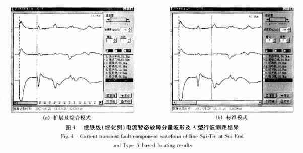
4. Conclusion In this paper, the A-type modern traveling wave fault location principle is divided into three independent operating modes: standard, extended and integrated, and various operating modes are used for actual faults by using the direct waveform analysis method of current transient components. Generated current transient waveform analysis. The actual failure analysis shows that the absolute distance error of the A-type modern traveling wave fault location principle does not exceed 500m.
Because some fault transient waveforms are more complex, it is not possible to obtain reliable ranging results directly in all operating modes. In order to further improve the reliability of the A-type modern traveling wave fault location principle, it is necessary to deeply study the real-time and reliable modern traveling wave detection and identification algorithm in combination with the actual fault transient waveform.
Modern Traveling Wave Fault Location Principle and Its Application in Fault Analysis of Actual Measurement
Introduction The transmission line traveling wave fault location technology has been paid attention to by relay protection professionals for its advantages of high ranging accuracy and wide application range [1]. As early as the 1950s, four basic types of traveling wave fault location devices such as A, B, C, and D were developed abroad. However, due to problems such as poor reliability, complicated structure, and high price, they were not widely used. .