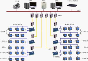
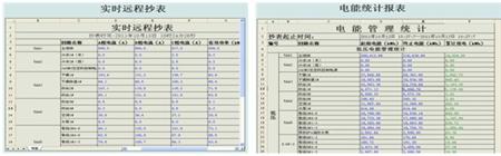
0, foreword With the rapid progress in the construction of the high-speed railway network and the departure of high-speed trains and trains into the lives of ordinary people, the Chinese government has incorporated energy-saving and emission-reduction targets into the medium and long-term plans for national economic and social development. It is committed that by 2020, the carbon dioxide emissions per unit of GDP in China will be 40% to 45% lower than in 2005. How to increase energy efficiency and achieve energy conservation and emission reduction targets are the basic principles for the design and construction of railway projects. Chengdu East Railway Station is currently the largest passenger transport hub in Southwest China with the most advanced facilities and the most advanced modernization. Chengdu East Railway Station is mainly used for the operation of the EMU passenger transport business of the Fucheng Railway and the operation of the express, fast and popular passenger transportation services of the Chengdu-Kunming Railway and the Baocheng-Chengdu Railway. Chengdu East Railway Station design integrates Jinsha culture and bronze mask elements and is directly under the Chengdu Railway Bureau. Chengdu East Railway Station is a large-scale modern comprehensive transportation hub integrating railway passenger transport, long-distance and tourist passenger transport, urban rail transit, urban public transport, rental and social parking. The station building project mainly includes elevated waiting floors, platform floors, and outbound floors. The (exchange hall) and the two-story subway will become Chengdu's important city function center. The following describes the energy management technology measures and actual results taken to ensure the high reliability and high security of the project in order to improve the operational efficiency and management level of the project's energy system, and achieve energy conservation and emission reduction targets. Figure 1 Overall appearance of Chengdu East Railway Station 1. Project Overview Chengdu East Railway Station is located in Chengdu Chenghua Development Zone, the third ring road Chengyu Interchange; this project is a key construction project in Chengdu in 2010, is one of the landmark buildings in the southwest. Chengdu East Railway Station includes East Plaza, West Plaza and station buildings. Chengdu East Railway Station covers an area of ​​about 45,333m2; the station has 14 platforms and 26 roads; the station area is about 108,000m2, with 5 floors, from top to bottom: waiting floor (3F), platform floor (2F ), Outbound Floor (1F), Ground Floor 2 (-1F), Ground Floor 7 (-2F). Chengdu East Railway Station Energy Management System Monitoring Range: Applies to the upper and lower 5 floors (including mezzanines) of the Dongzhan station. Smart meters on all power cabinets (Shanghai Ankerui PZ80L-E4/K, ARTU-K32). 2. Energy Management Needs Analysis As Chengdu East Railway Station is a large modern integrated transportation hub, which requires high reliability and safety of the system, intensive load, and large power supply capacity, it also puts forward corresponding requirements for the energy management system: a Extremely high security and reliability. Comprehensive transportation hub operations will surely bring a large number of people to gather, and put forward high requirements for ensuring safety and continuous and reliable operation of lighting, ventilation and other systems. b Continuous and stable operation for a long time. The function of comprehensive transportation requires that the station building facilities must be able to ensure long-term, stable and stable operation, which requires the stable operation of the energy management system. c Energy cost control requirements. The level of user-friendly facilities and the satisfaction of comfortable experience in use will inevitably bring about great energy consumption for air conditioning and lighting ventilation. It is necessary to classify and monitor energy consumption and make reasonable adjustments to actual passenger flow changes to reduce overall operating costs. d Requirements to reduce the intensity of overall facility operations management. As for the comprehensive transport facilities of the Chengdu East Railway Station integrated transportation hub, such as large-scale, wide-distribution facilities, and high passenger flow density, the day-to-day operation management intensity is very high. The traditional station management model cannot satisfy the normal functions and reliability. The requirements of safeguards must be based on modern automation techniques to improve management efficiency. e Adapt to development and improve the management level. China's high-speed rails represent the world's leading level of railway facilities, requiring that the corresponding facilities management level be upgraded accordingly in order to fully realize the functions of the facilities. To meet the above requirements, dynamic energy management technology must be used to conduct comprehensive real-time monitoring and management of the facility's overall energy system to provide facilities operation management tools and energy management tools. To integrate the facilities and architectural features of the Chengdu East Railway Station Railway Terminal Station and the above requirements, it is necessary to realize the functional requirements for comprehensive management of its energy system. The energy management system technology program should have the following characteristics: a Special requirements for system capacity due to the large scale of the facility. The railway station at Chengdu Dongzhan Railway Station has huge facilities, a wide distribution of space, a wide variety of energy systems, and a wide and complex distribution of energy-consuming equipment. Therefore, the number of energy-consumption and energy-efficiency parameter detection points involved in this project's energy management system is extremely large, resulting in systems. The total capacity requirement greatly exceeds the size of the general system, and special requirements are also placed on the scale and design of the system's real-time database and historical database. b Wide distribution of space requirements for communication networks. There are many energy consumption and energy efficiency parameters and a wide range of points. A large amount of data is transmitted from the end of the distribution link to the back end of the system. This requires that the network has sufficient communication bandwidth to ensure real-time transmission and storage of classified energy consumption data for each partition, and to achieve data synchronization. And interoperability. Therefore, the system communication network must have high reliability and scalability. c Multi-energy system requirements for system development and scalability. The multi-energy system of the Chengdu East Railway Station's integrated transportation hub requires that its energy management system be sufficiently open, with compatible and open interfaces and databases integrated with other systems, to facilitate the interface with other systems, and to achieve data sharing. d The requirements of the complexity of the energy consumption load on the suitability of the testing equipment. High-speed rail hub internal load devices are complex and diverse, require energy and energy efficiency monitoring equipment sufficient robustness and reliability, can adapt to harsh environment requirements, require voltage and current waveforms in the case of severe distortion can also quickly and accurately collect data. 3 Solution 3.1 Overview Based on the above demand analysis, combined with the building characteristics of the Chengdu East Railway Station railway junction station, the project selected Acrel-5000 full-time dynamic energy management technology for project design. The overall architecture adopts a hierarchical distributed structure, which consists of the central monitoring room master station system, the backbone communication network and the data network of the measurement and control layer, and the bottom energy consumption and energy efficiency monitoring equipment. 3.2 System Architecture The system topology is shown in Figure 2. From top to bottom, the system layer, data network layer, and measurement and control layer are included. Figure 2 System topology As shown in the figure, the communication cable of the IO equipment in the site is connected to the RS485 communication interface of the on-site intelligent device using RVSP 2*1.5 shielded twisted pair, and the maximum number of instruments connected to each bus is 32 sets. There are communication collection boxes in the 6 weak machine rooms on the site. Intelligent devices in the power cabinets and wall cabinets are connected to the nearby communication collection box, and then uploaded to the central control room through the optical fiber. The host computer monitors the uploaded data in the background. Acquisition processing. 3.2.1 Energy Management System Master Station The device list is shown in Table 1: name Model, specification unit Quantity Note Workstation host EVOC IPC-810B Core2 2.66G / 2G / 250G + keyboard and mouse station 2 Yanxiang monitor 19W "LCD Monitor station 2 Samsung UPS power supply C2K/2KVA standby 60 minutes tower station 1 SANTACK printer HP 1007 A4 format station 1 HP system software Genuine Microsoft WINDOWS XP/SP3 set 2 Microsoft Communication cabinet 8U wall cabinet surface 12 Local procurement Communication cabinet K1200 (1166*600*600) set 1 Local procurement Console Steel-wood structure with two chairs set 1 Local procurement Power Management Software System configuration software Acrel-5000V6 set 1 Ankerui Power monitoring software Data Storage Software Acrel-dbSQL set 1 Ankerui Power Management Software Energy Management Software Acrel-EnerSys set 1 Ankerui Power monitoring software Device Driver Software Acrel-Driver station 1 DELL Table 1 Energy Management System Master Equipment List In the central monitoring room of Chengdu East Railway Station, the system server (main/standby dual system) is set up. The system control computer adopts windows XP operating system. The application software uses Acrel-5000 system-specific configuration software to realize normal monitoring data and remote power distribution equipment. Concentrated state presentation, recording and analysis of accident processes, switching operations, data storage, statistical analysis and processing of data, data sharing between multiple systems, accident alarms, etc.; configuration of a laser printer, can print a variety of graphics generated by the software, Screens, reports, accident reports, load curves, etc.; configuration of a UPS uninterruptible power supply equipment, can deal with emergency power supply interruption, to avoid the loss of system data; the system master station through the optical Ethernet network with the lower equipment connection. 3.2.2 Backbone Data Communication Network The device list is shown in Table 2: name Model, specification unit Quantity Note Industrial network switch TP-LINK 16 ports station 1 TP-LINK Industrial Serial Server NPORT5232I RS485 interface × 2 with light isolation set 12 MOXA Photoelectric converter Single mode photoelectric conversion HTB-1100S(25km) set twenty four Zhao Yue Industrial switching power supply KDYA-DG75-24 set 12 Huali Table 2 List of Network Communication Layer Devices The backbone network adopts a ring topological structure, and data transmission between the master station and the substations is achieved by single-mode optical fibers with 6 or more cores. Optical transceivers are used to convert optical and electrical signals. 3.2.3 Measurement and control layer data bus network The RVSP 2*1.5 (shielded twisted pair) connects the bottom energy consumption and energy efficiency monitoring units to the distributed communication substations to form an energy monitoring and control layer bus network to transmit real-time data on energy consumption and energy efficiency of load equipment. 3.2.4 measurement and control layer hardware devices (see Figure 4) Distribution in the energy system at the bottom of the load device, to achieve load device energy consumption and energy efficiency monitoring, including: smart power consumption and energy efficiency monitoring unit to ensure that the environment is more adaptable and a large number of real-time data acquisition, monitoring, with bus communication capabilities. Device Name: PZ80L-E4/K                            model Functional characteristics PZ80L-E4/k Measurement the amount Senate number Three-phase current ■Three-phase voltage ■Grid frequency ■Three-phase (active power, reactive power, power factor) ■Three-phase (active energy, reactive energy) ■Optional function (Optionally) C □ KC(2DI/2DO) □ KC(4DI) □ ■as standard, □ as optional Table 3 Field equipment layer instrument technical parameters 3.3 System Functions 3.3.1 Initial System Initial Interface After the system runs successfully, it enters the operation interface. The system provides a simple, easy-to-use, and good user interface. The on-duty personnel can view the remote device status (opening/closing) and remote measurement (current) of the smart device in the sub-area after logging in. , voltage, active power, reactive power, power factor, power). 3.3.2. Real-time electrical parameters in different regions Log in ordinary users, through the operation of the main interface, you can view the electrical parameters (current, voltage, active power, reactive power, power factor, power,) of each area running, and change the closing status of each circuit through the data of the loop. Changes are displayed (red for closing, green for breaking). At the same time, each loop supports the curve query function. Through the operation of this interface, each current trend curve can be queried. 3.3.3 System Remote Alarm Status Alarm In the event of an operational failure in the distribution system, an audible and visual alarm will be promptly issued to prompt the user to respond to the fault circuit in a timely manner. At the same time, the time and loop name of the event will be automatically recorded so that the on-duty personnel at the station can query and recall the cause of the fault. 3.3.4 Trend Curve Analysis The Acrel-5000 energy management system provides two curve analysis interfaces for real-time and historical trends. The current load status of the circuit is analyzed by calling the relevant loop real-time curve interface. For example, by invoking the real-time curve of a given loop, the signal fluctuation caused by the electrical equipment of the loop can be analyzed. The historical trend of the system is that the system can view its historical trend for all stored data, which facilitates quality analysis of the monitored distribution network by station attendants . 3.3.5 Report Statistics Active power level data collected by the system, according to the names of different circuits, automatic report generation and report printing function there can be queried and printed for a period of time of a circuit electricity consumption, but these statements can in Excel The format is exported and the history is retained for more than 3 years . 3.3.6 Other functions Other day-to-day management, such as operation records and shift record management, equipment operation status, defects, maintenance records management, rules and regulations. Management functions meet user requirements, application, convenience, and resource sharing. Various documents can be stored, retrieved, edited, displayed, and printed. 4 Preliminary assessment of effects The design and operation of the system reduces maintenance personnel's workload and labor intensity, improves work efficiency, helps the station to arrange maintenance schedules rationally, reduces costs, provides early warning of hidden dangers, prevents accidents, and ensures normal operation of production. All kinds of data, drawings, and reports realize electronic informationization to achieve real-time remote control of all power parameters and status information, providing first-hand information for improving power quality and power supply reliability. Information expansion and interconnection can be achieved. As part of the Intranet, seamless connectivity with BAS systems or plant-wide MIS can be achieved. 5 Summary With the development of society and the wide application of electricity, the energy management system has become an inevitable choice for large-scale multi-substation users, such as key construction projects, landmark buildings, and large-scale public facilities throughout the country. The Acrel-5000 energy management system introduced in this paper is introduced. The application of the Chengdu East Railway Station can realize the real-time monitoring of the low-voltage power distribution circuit. It can not only show the power status of the circuit, but also has the network communication function, but it can perform the data remote function. The system realizes the analysis and processing of the collected data, displays the running status of each distribution circuit in real time, has a pop-up alarm dialog box and voice prompts for the closing and closing of the load, and generates various energy reports, analysis curves, graphics, etc. It is convenient for remote meter reading as well as analysis and research. The system is safe, reliable, and stable. It provides a reliable basis for the application of electricity to large-scale public buildings and has achieved good social benefits. references: [1] Ren Zhicheng, Zhou Zhong. Principles and Application Guide for Power Electronic Measurement Digital Meters [M]. Beijing. China Electric Power Press, 2007. 4 [2] Xu Yi Comprehensive Energy Saving of Building Electrical System[J]. Modern Building & Electric, 2010,1(2):1-4,22. About the Author: Xu Shuang, female, undergraduate, Ankerui Electric Co., Ltd., the main research direction for the smart grid power distribution, Email: Mobile QQ "Atlas of Design and Application of Building Energy Consumption Monitoring and Management System" (atlas number: ACR12CDX301) edited by Ankerui Electric Co., Ltd. and Shandong Construction Electrical Technology Information Network, this atlas combined with Acrel-5000 energy consumption The monitoring system complies with the electrical design specifications and meets the requirements for the construction of energy-saving supervision systems for office buildings and public buildings of state agencies, to achieve the scientific and data-based management of green building energy use, and to achieve the goal of saving energy and reducing consumption of green buildings. The Atlas is applicable to the system design, construction, operation and maintenance of energy monitoring and management of office buildings and public buildings of newly-built or rebuilt national offices. If you need atlas, please provide your organization's name, department, address, zip code, contact person, contact telephone number, email address, fax 021-69155331, mail or QQ to Ankeru Xu cream engineer, Ankerui Electric will give you a free gift. . Citric ACID is white or almost white, crystalline powder, colourless crystals or granulars, odoless has a strongly acid taste, very solubleinwater, freely soluble in ethanol. It`s mainly used as acidulant,flavoring agent, preservative and antistaling agent in food and beverage industry. anhydrous citric acid,citric acid mono,citric acid solution Yucheng Jinhe Industrial Co.,Ltd , https://www.hnironoxide.com
 The system enters the operation phase and displays the progress bar. This enables the user to accurately check the progress of the system operation and prevent the system from running completely. The user operation causes data transmission error.
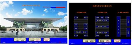


It is also used as antioxidant,Plasticizer and Detergent in chemical,cosmetics and cleaning industries.
Introduction of Chengdu East Passenger Station Distribution Energy Management System in Southwest Railway Passenger Terminal