Chongqing Huanyu Automobile Sales Company , https://www.huanyuauto.com
Intro to Relays #2 - ANSI/IEEE Relay Numbers
Protective relays represent a complex yet essential field within electrical engineering and contracting. While they might seem daunting at first glance, understanding them doesn’t have to be overwhelming. This series of three articles aims to demystify the basics of relaying for professionals in the solar and energy storage sectors who aren’t engineers.
**Introduction to Relays #1: What Are Relays, CTs, & PTs?**
**Introduction to Relays #2: ANSI/IEEE Relay Device Numbers (Find Below)**
**Introduction to Relays #3: What Does SEL Stand For?**
---
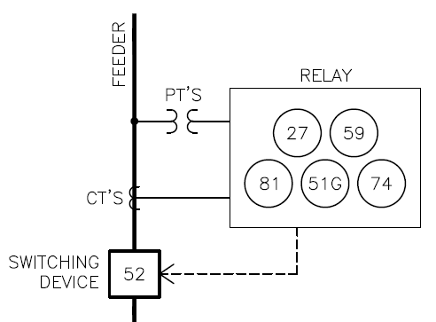
### **Relay Numbers**
Protective relays are designed based on standardized device numbers that define their functionalities. Instead of lengthy verbal descriptions, these numbers serve as shorthand for various relay functions. The numbering system follows the guidelines laid out in ANSI/IEEE C37.2.
#### **Why Use Numbers Instead of Words?**
1. **Efficiency**: Using numbers streamlines communication and diagram creation. For example, saying "59N" is far quicker than explaining "overvoltage on the neutral."
2. **Standardization**: Numbers ensure universal understanding across different teams—whether they’re utilities, engineers, vendors, or installers. Miscommunication becomes less likely.
3. **Compactness**: Given that relays often perform multiple functions, labeling them with numbers makes schematics cleaner and easier to read. Take, for instance, a relay handling "phase overvoltage & undervoltage, phase overfrequency & underfrequency, ground inverse-time overcurrent, and alarms." Writing out all those descriptions would be cumbersome compared to simply listing the corresponding numbers.
---
### **Relay Functions Commonly Used in Solar Projects**
Below are some frequently encountered relay functions in photovoltaic (PV) and energy storage systems:
| # | Name | Description |
|-----|--------------------------|-----------------------------------------------------------------------------|
| 25 | Synchronizing Clock | Compares utility and solar circuit voltages, frequencies, and phase angles. If matched, it allows solar connection to the grid. |
| 27 | Undervoltage | Activates when voltage falls below a preset threshold. |
| 32 | Directional Power | Triggers if power flow exceeds a set limit in a specific direction (reverse power relay). |
| 49 | Transformer Thermal | Alerts when the winding temperature surpasses a set value. |
| 50 | Instantaneous Overcurrent| Activates when current exceeds a predefined value. |
| 51 | Inverse-Time Overcurrent | Triggers after a set duration if current exceeds a specified value. |
| 52 | Circuit Breaker | Opens a circuit. Adding 'R' indicates it can also reclose the circuit. |
| 59 | Overvoltage | Activates when voltage goes above a set point. |
| 74 | Alarm | Initiates visual, audible, or data-based alarms. |
| 79 | AC Reclosing | Manages reclosing or locking out of AC circuit interrupters. |
| 81 | Frequency | Activates when frequency strays outside acceptable ranges. |
| 86 | Lockout | Prevents operation until manually reset. |
| 87 | Differential Protective | Triggers when there’s a discrepancy between two measured currents. |
| 89 | Line Switch | Refers to devices like disconnect switches. Adding '89' typically requires electrical accessories. |
---
### **Letters After the Numbers**
Sometimes, letters are appended to the numbers to specify additional features:
| # | Name | Description |
|-----|---------|-----------------------------------------------------------------------------|
| R | Reclosing | Adds the ability to reclose circuits. Example: 52R is a circuit breaker capable of opening and reclosing. |
| P | Phase | Indicates the function operates on the phases. By default, many functions apply to phases unless otherwise stated. |
| N | Neutral | Specifies the function applies to the neutral instead of the phase. Example: 51N monitors neutral for unbalanced overcurrent. |
| G | Ground | Indicates the function targets the ground rather than the phase. Example: 51G checks ground bonding for ground faults. |
---
### **Setpoints**
Simply identifying the functions isn’t enough; every function needs associated minimum and/or maximum setpoints. These values are determined by engineers and often vary from one project to another.
---
### **Conclusion**
On a broad scale, relay device numbers offer a straightforward concept. Yet, delving deeper reveals layers of complexity. Fortunately, developers and project managers don’t need to master these intricacies to succeed—they can rely on seasoned experts like Pure Power. If your project requires assistance with relays, feel free to explore our resources [here] or contact us directly today!
---
*P.S. Engineers looking for stimulating technical discussions should check out Pure Power’s openings. Our team of 80 engineers has designed over 2,000 commercial and industrial (C&I) and utility-scale solar projects. Joining us could be your next big step.*
